The idea was born from a mishap
Coming home to discover that, while we were away, a fault caused a power outage can turn into a serious problem: the freezer thaws out, the fish tank filter stops, the alarm system battery drains. That’s exactly what happened to us, and that’s where the idea came from: building a device that could warn us by SMS, with a short delay relative to the event (more on what causes that further down), even while we’re away from home.
In this project we’re once again using our favourite GSM module, the SIM800L. For details on how it works in general, the basic wiring and the most common AT commands, see our dedicated guide: Complete guide to the SIM800L GSM module.
Update: this is version 2 of the project. Compared to the first publication we fixed a bug in the sensor-reading circuit (reported by some readers in the comments — thank you!), added a real-time clock (RTC), low-power sleep mode, an input protection fuse, a level shifter for the GSM module’s serial line, an OLED display that shows the device’s status at a glance, and the complete firmware, which was missing before. Along the way we also found and fixed two mistakes of our own — the wake-up from sleep and the battery voltage reading — which we cover in full in the dedicated sections.
Why build it yourself
Off-the-shelf remote monitoring systems and “smart” plugs with power-loss notifications already exist. They cost less time, but typically require a cloud subscription, a proprietary app and an always-on Wi-Fi connection (which, in many cases, goes down together with the mains power). Building your own costs a few extra evenings, but gives you back three things a closed solution doesn’t: really understanding how it works, being able to modify every part of it (thresholds, phone numbers, alarm logic), and, not least, the satisfaction of having solved the problem with your own hands.
How a device like this works
A power-outage SMS detection system, in general, has to handle four things:
- Detect the interruption: stay constantly connected to the mains and notice when the voltage disappears.
- Warn: send an SMS with the event information, with a precise date and time.
- Report the restoration: warn when power comes back, stating how long it was out.
- Stay on during the outage: this requires a backup battery that recharges while mains power is present.
Off-the-shelf commercial solutions obviously already exist, but the satisfaction of building one from scratch, understanding every component and being free to customise it is absolutely worth it.
In our version we add a fifth element, not essential but very handy: a small OLED display that shows, with no need to connect a computer, whether the mains is present, how much charge the battery has, and whether the GSM module is registered on the cellular network.
The hardware
Arduino Nano
The heart of the system. Compact, cheap, with more than enough pins for this project. We use the “commercial” version based on the ATMEGA328P, which lacks the protections of the original boards: handle it with care while prototyping. It uses the CH340G USB-to-serial converter, which needs dedicated drivers installed.
5V USB BMS module for LiPo battery (TC4056A)
Handles both charging the battery and distributing power to the whole system. It takes 5V/2A from a common smartphone charger and, through the optocoupler, also lets us “read” whether mains voltage is present. Includes overcharge and short-circuit protection.
Input protection fuse (new in v2)
Ahead of the BMS we added a self-resetting 1.1A PTC fuse. Unlike a traditional fuse, it doesn’t need replacing after tripping: it “resets” automatically once the overcurrent cause is removed. It’s a cheap but important protection, preventing damage to the BMS and the battery in case of problems with the power adapter or an accidental short circuit during assembly.
MT3608 step-up converter
The BMS module always outputs the battery voltage (3.7V), even when mains power is present: it has no built-in step-up. The MT3608 module converts this voltage to a stable 5V to power the Arduino. On the output we add a 100µF electrolytic capacitor to further stabilise the voltage.
The trimmer needs to be calibrated before connecting the Arduino. The output should be adjusted to 5.0V measured with a multimeter, before connecting anything else, because the module isn’t guaranteed to arrive already set to that value. Ours wasn’t, and we found out the hard way: from a battery reading that didn’t add up. The full story is in the dedicated section further down.
PC817 optocoupler
The most delicate component in the project. It contains an LED and a phototransistor in the same package and lets a signal pass between two circuits with no direct electrical contact, physically isolating the low-voltage side from any disturbance on the power side.
3.7V LiPo battery
Powers the system during the outage. It must always be managed through a BMS with overcharge/short-circuit protection: LiPo cells, if mistreated, can get damaged or catch fire.
SIM800L GSM module
Handles the actual sending of SMS messages. While transmitting it can draw peaks of up to 2A: it must be powered directly from the battery (never from the Arduino’s 5V pin) and protected with a capacitor of at least 2200µF as close as possible to its power pins. Its TX/RX serial lines run at 3.3V, while the Arduino Nano runs at 5V: the next paragraph explains how we connect them. For power, basic wiring and the essential AT commands, see our dedicated guide: Complete guide to the SIM800L GSM module.
Two notes on our build. First: the sketch talks to the module at 9600 baud. If your SIM800L was left configured at a different speed (our old test used 57600 baud) it won’t respond to commands, and the display will show SIM800L: ASSENTE (“SIM800L: absent”). Second: the module’s DTR and RST pins aren’t connected to the Arduino, so there’s no hardware sleep for the SIM800L, which stays always on and registered on the network.
3.3V–5V logic level shifter module (new in v2)
The SIM800L works at 3.3V logic levels, while the Arduino Nano is at 5V: the two serial lines (TX and RX) therefore need adapting. In the very first draft of this project we’d planned a simple resistive divider on the RX line only (the one receiving 5V data from the Arduino), leaving the TX line connected directly. It works, but it’s a compromise: the divider gives an “attenuated” level rather than a clean 3.3V, and it’s asymmetric anyway (one line protected, the other not).
Having a bidirectional logic level shifter module in the lab (the common 4-channel modules based on the BSS138 MOSFET, of which 2 channels are enough), we chose to use it for both lines, TX and RX: it produces clean levels (0V/3.3V) instead of an intermediate voltage, and it’s a component designed exactly for this purpose, with better safety margins than two resistors put together as needed. The HV (high-voltage) side connects to the Arduino’s 5V rail, the LV (low-voltage) side to the Arduino Nano’s 3V3 pin (the on-board regulator supplies more than enough margin for a level-translation chip), with GND shared across the whole system.
Nothing changes at the firmware level: pins D7/D8 and the software serial communication stay exactly the same, because the level shifter is transparent to the code — it only translates the voltage, not the protocol.
DS3231 RTC (new in v2)
The Arduino has no persistent clock of its own: if we power it up from scratch it doesn’t know what time it is, and after a long outage it would lose track anyway if it relied only on millis(). The DS3231 module, connected over the I2C bus, is a dedicated hardware clock with very high accuracy (typically within a few seconds a month) and a small CR2032 backup battery that lets it keep counting time even with the system off. Thanks to this module, every SMS now reports the event’s real date and time, and the outage duration is calculated precisely. As we’ll see in the software section, the time is also re-synced to the PC’s clock on every new upload of the sketch.
SSD1306 128×64 OLED display (new in v2)
A device that patiently waits for a power outage has one flaw: from the outside you can’t tell if it’s working. That’s why we added a small 0.96″ OLED display, with an SSD1306 controller, that shows at a glance what’s going on.
It connects to the same I2C bus as the DS3231 (SDA on A4, SCL on A5, power and GND): the display’s typical address is 0x3C, the DS3231’s is 0x68, so there’s no conflict. The sketch checks whether the display is present on the bus at startup: if it’s missing, the blackout monitor still works, because the protection shouldn’t depend on a screen.
The screen has 8 rows of 8 pixels, with 16 characters per row. Here’s what it shows:
text
19/09/2026 16:52      date and time (hh:mm)
Rete elettrica:       ("Mains power:")
ONLINE                mains status (double-size characters) / OFFLINE
Batteria: 3.63V       ("Battery: 3.63V") — A0 reading via the divider
Arduino: SLEEP        ACTIVE on wake-up, SLEEP just before sleeping
SIM800L: ATTIVO       ("SIM800L: ACTIVE") if it responds to AT commands, else ASSENTE ("absent")
GSM: CONNESSO         ("GSM: CONNECTED") from AT+CREG?: CONNECTED / SEARCHING… / NO NETWORK / --
A couple of clarifications, because some lines can be read the wrong way. The mains status shown is the one confirmed by the debounce, not the instantaneous pin reading. The Arduino: ATTIVO (“Arduino: ACTIVE”) label only appears while the microcontroller is awake: during sleep the display keeps showing the last image on its own, so the sketch writes SLEEP an instant before falling asleep and ATTIVO as soon as it wakes up. If the SIM800L isn’t connected, the display shows ASSENTE and GSM: --. Every row is padded with spaces and rewritten without clearing the screen, so there’s no flicker.
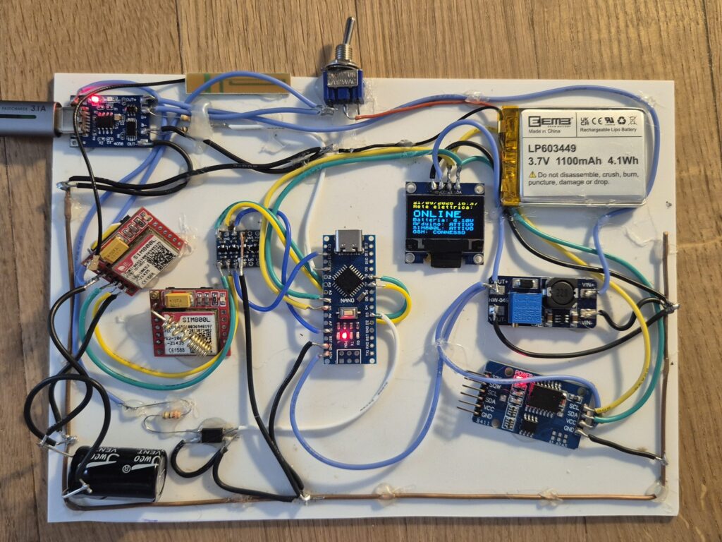
The display lit up on the prototype: one glance is enough to know mains, battery and GSM module are all fine.
Why U8g2 in U8x8 mode. The most common library for these displays, Adafruit_SSD1306, keeps a full-screen buffer in RAM: 1 KB. The ATmega328P has 2 KB of RAM in total, and with the starting v2 sketch there were only about 1,100 bytes free: the buffer doesn’t fit. U8g2 in U8x8 mode writes only text, directly to the display, with no buffer at all. On top of that, all fixed strings stay in flash thanks to the F() macro.
The price to pay. An OLED that’s always on draws, by estimate, about 10–15 mA: an order of magnitude to be confirmed with our own measurement (see the testing section). That’s not nothing for a battery-powered device. Contrast is adjusted with the OLED_CONTRASTO constant (lower means less power draw and less panel wear), and anyone chasing maximum runtime can simply not fit the display.
📷 Our prototype
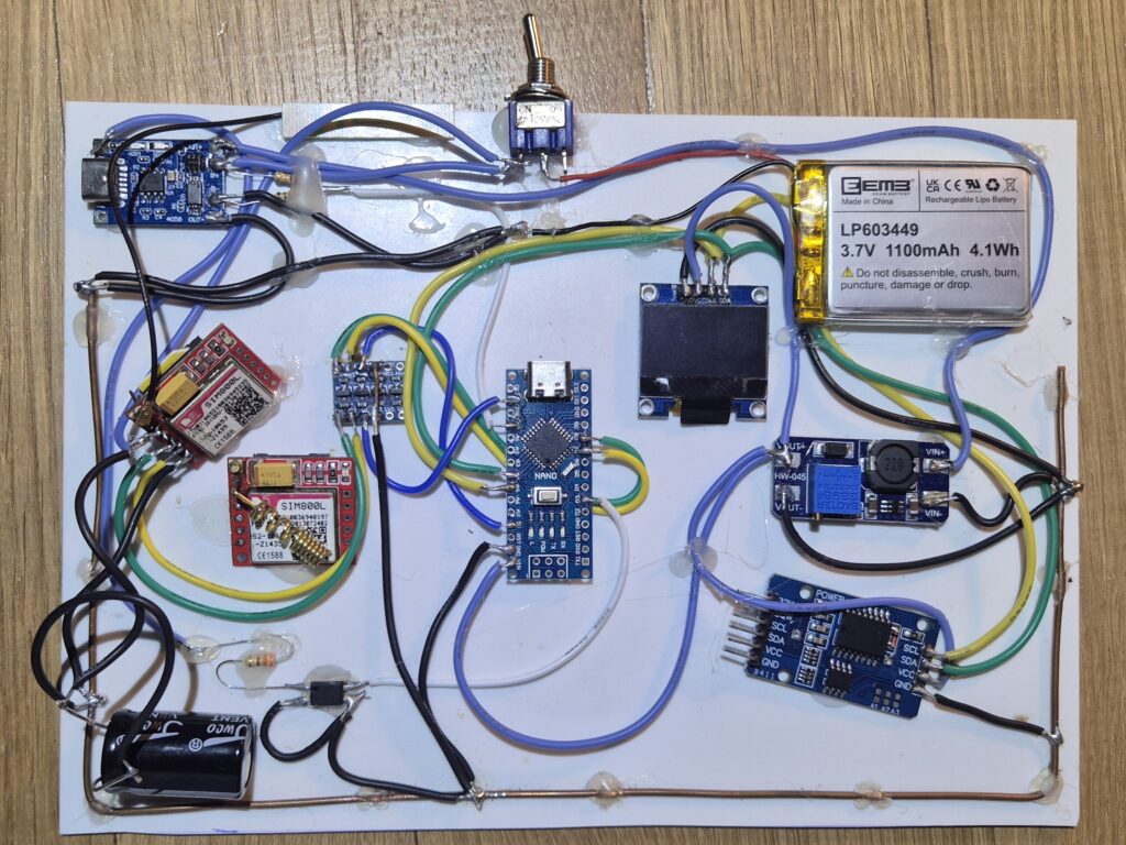
The real prototype, built on perfboard before its final home in the enclosure. It’s not perfect — and it’s right that it shows.
Bill of materials (BOM)
Here’s the complete list of components needed to build the project, including the values of the passive components discussed in the circuit diagram.
Note: as an Amazon Associate we earn from qualifying purchases made through these links, at no extra cost to the buyer.
| # | Component | Specs | Qty | Notes | Amazon link |
|---|---|---|---|---|---|
| 1 | Arduino Nano | ATmega328P, CH340G clone | 1 | Remember the CH340G drivers | Link Amazon |
| 2 | TC4056A USB BMS module | 1S LiPo charging, OCP/OVP protection | 1 | USB-C or micro-USB input | Link Amazon |
| 3 | MT3608 step-up | Adjustable DC-DC boost | 1 | Set the output to 5.0V measured with a tester (trimmer), before connecting the Arduino | Link Amazon |
| 4 | PC817 optocoupler | LED + phototransistor optoisolator | 1 | Link Amazon | |
| 5 | 3.7V LiPo battery | Capacity based on desired runtime (min. 1500mAh recommended) | 1 | With JST connector compatible with the BMS | Link Amazon |
| 6 | SIM800L GSM module | With antenna | 1 | Check your carrier’s 2G coverage in your area | Link Amazon |
| 7 | DS3231 RTC module | With CR2032 backup battery included | 1 | I2C bus | Link Amazon |
| 8 | 0.96″ SSD1306 OLED display | 128×64 pixels, I2C interface | 1 | Typical address 0x3C; same I2C bus as the DS3231. Optional: the firmware works without it too | Link Amazon |
| 9 | Self-resetting PTC fuse | 1.1A (or a traditional fast fuse + fuse holder) | 1 | On the 5V input, before the BMS | |
| 10 | Resistor R1 | 330 Ω, 1/4W | 1 | In series with the PC817’s LED | |
| 11 | Resistor R3 | 100 kΩ, 1/4W | 1 | RC filter on D3 | |
| 12 | Capacitor C3 | 100 nF ceramic | 1 | RC filter on D3 | |
| 13 | Capacitor C1 | 2200 µF, 10V, low-ESR electrolytic | 1 | Close to the SIM800L’s power pins | |
| 14 | Capacitor C2 | 100 nF ceramic | 1 | SIM800L decoupling | |
| 15 | Capacitor C4 | 100 µF electrolytic | 1 | Step-up output filter | |
| 16 | Resistors R_alto / R_basso (“R_high” / “R_low”) | 10 kΩ, 1/4W (x2) | 2 | Battery-monitoring divider on A0 | |
| 17 | Bidirectional logic level shifter module | 3.3V–5V, BSS138 type, min. 2 channels (the common 4-channel modules work fine) | 1 | Replaces the RX divider; used on the SIM800L’s TX and RX | |
| 18 | 5V / 2A power adapter | Smartphone-charger type, USB-A or USB-C | 1 | ||
| 19 | Voice/SMS-only prepaid SIM | With PIN disabled | 1 | Check remaining credit periodically | – |
| 20 | Perfboard or prototyping PCB | 1 | |||
| 21 | Electronics enclosure/case | Size based on final footprint | 1 | ||
| 22 | Wiring and Dupont connectors | as needed |
Reasoning behind the main hardware choices
Why Arduino Nano and not ESP32. The ESP32 would offer built-in Wi-Fi/Bluetooth and, potentially, notifications over the internet as well as by SMS. For this specific project, though, we preferred the Arduino Nano’s ATmega328P: deep-sleep management is simpler and better documented (direct Watchdog registers, without the complexities of ESP32’s deep sleep), power-down consumption is extremely predictable, and 5V logic interfaces more straightforwardly with modules like the PC817 without having to think about the 3.3V levels typical of the ESP32. Anyone who’d still rather start from an ESP32 will find pointers in the dedicated FAQ further down.
Why SIM800L and not an LTE/NB-IoT module. The SIM800L remains a cheap, well-documented choice with a very large community behind it. Its most concrete limitation is the progressive shutdown of 2G networks by some carriers: local 2G coverage should be checked before starting the project. An LTE Cat-M1/NB-IoT module would be more future-proof, but has higher cost and programming complexity — a possible future development rather than a baseline choice.
Why an optocoupler and not a simple resistive divider. A resistive divider connected directly to the rectified mains voltage would work, but it would put the low-voltage side (the Arduino) in direct electrical contact with the mains-connected side. The PC817 introduces real galvanic isolation between the two worlds: a safety requirement we consider non-negotiable, even in a hobby project.
Why a dedicated level shifter and not a resistive divider on the RX line. A divider works, and it was the planned solution in the project’s initial draft: two resistors (10kΩ/20kΩ) are enough to bring the Arduino’s 5V down to a level the SIM800L reads as HIGH. The problem is that it remains a compromise: the output level isn’t a true 3.3V but an intermediate value calculated to stay above threshold, and it’s an asymmetric solution anyway, since the TX line (from the SIM800L to the Arduino) stayed connected directly. Having a bidirectional level shifter module available, we preferred it on both lines: it returns clean logic levels (0V/3.3V and 0V/5V) instead of a resistive compromise, with a bigger safety margin for the GSM module.
Why an external RTC and not the SIM800L’s network time. The SIM800L can in theory retrieve the time from the GSM network, but that requires synchronisation that depends on coverage and carrier, and isn’t always reliable. A dedicated RTC like the DS3231 is cheap, doesn’t depend on the cellular network, and is accurate regardless of what’s happening with the GSM module at any given moment — an important requirement for a device that needs to stay reliable exactly when the other infrastructure (power, network) is in trouble.
Why a display, despite the power draw. A device that protects the house while we’re away still needs to be checked on now and then: knowing at a glance that the mains is present, the battery is charged and the GSM module is registered is worth, to us, more than the extra few milliamps. But if runtime during an outage is the absolute priority, the display is the first thing to remove or dim: the firmware is written to work identically without it.
The circuit diagram: the part we got wrong
In the first version of this article, several readers (thank you Francesco and Mario!) flagged doubts about how the PC817 was wired to the Arduino’s D3 pin. They were right: the original configuration produced about 450mV on the digital pin when mains power was present — a value that the ATmega328P doesn’t read as HIGH, but as LOW (the minimum threshold for HIGH at 5V logic levels is about 3V). The signal was too weak to be read reliably.
The fix, simpler and more robust than the original version, uses the PC817’s phototransistor in an open-collector configuration with the Arduino’s internal pull-up resistor (INPUT_PULLUP):
- Mains present → PC817 LED on → phototransistor conducting → D3 pulled to GND (clean LOW)
- Blackout → phototransistor off → internal pull-up brings D3 to 5V (clean HIGH)
On top of this, in v2 we added a small hardware RC filter (R3 100kΩ + C3 100nF) between the PC817’s output and pin D3, with a time constant of about 10ms: it dampens fast electrical disturbances before they even reach the Arduino, taking some of the load off the software debounce.
Complete circuit diagram (v2)
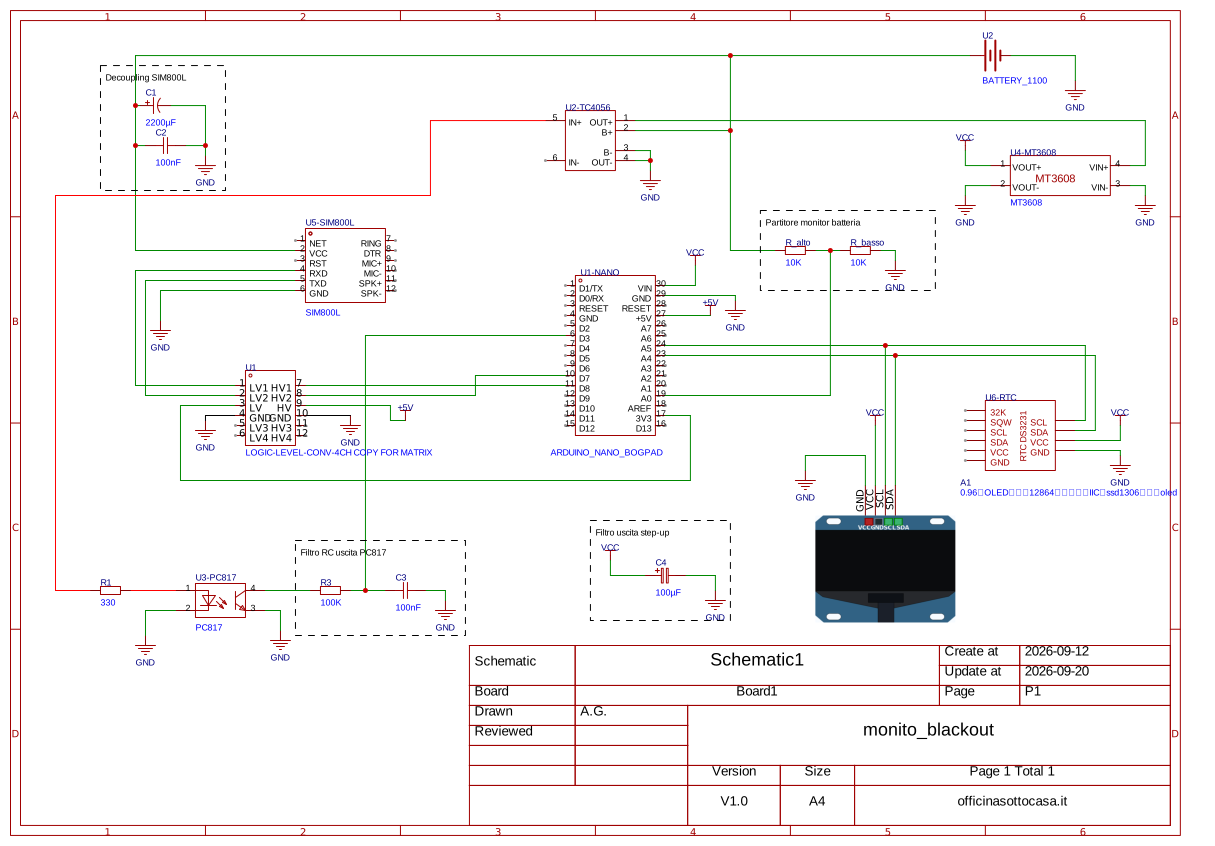
The project’s complete circuit diagram, with all passive component values (resistors and capacitors), made with EasyEDA.
In the diagram you’ll find:
- the position and value of every resistor: R1 = 330Ω (limits the PC817 LED’s current), R3 = 100kΩ (RC filter on D3), R_high and R_low = 10kΩ (battery-reading divider on A0)
- the position and value of every capacitor: C1 = 2200µF and C2 = 100nF (SIM800L decoupling), C3 = 100nF (RC filter on D3), C4 = 100µF (step-up output filter)
- the DS3231 RTC module and the SSD1306 OLED display on the same I2C bus (SDA on A4, SCL on A5)
- the 3.3V–5V logic level shifter module on the SIM800L’s TX/RX lines (D7/D8), with the HV side on 5V and the LV side on the Arduino’s 3V3 pin (replacing the R5/R6 divider originally planned)
- the SIM800L’s direct power point from the battery, with C1 and C2 close to its pins
- the wiring of the input PTC fuse F1, ahead of the BMS [TO BE ADDED TO THE DIAGRAM: not yet drawn in the current PDF]
How it works
- Measurement: since this is a 5V-powered system, no real voltage sensor is needed: it’s enough to know whether it’s present or not.
- Isolation and conversion: the PC817 optocoupler converts the presence/absence of mains voltage into a digital signal, while keeping the two circuits physically separate.
- Filtering: a hardware RC filter (R3 + C3) removes the fastest disturbances before the signal even reaches the Arduino.
- RTC-based software debounce: the new state has to stay stable for several consecutive seconds, checked against the RTC clock (not
millis(), which stops during sleep — see the dedicated section), before being treated as a real event. - Display: as soon as the state is confirmed, the OLED display updates, before the SMS is even sent (which takes several seconds).
- Alert: once confirmed, the microcontroller sends an SMS via the GSM module, with a precise date and time.
How much delay is there between the outage and the SMS
The SMS doesn’t go out the instant power is lost, and that’s not a flaw: it’s the price of a system that doesn’t get fooled by a momentary blip. The delay has three sources, and it’s clearly visible in the testing video.
- The PC817’s LED doesn’t turn off immediately. The optocoupler’s LED is powered from the adapter’s 5V line, through R1. When mains power is lost, that voltage doesn’t drop instantly: the adapter and the BMS input typically contain capacitors that keep it up for a little while, and the LED stays on until the current drops below its conduction threshold. The RC filter (R3 and C3) only adds about 10ms. Measured delay: INSERISCI-RITARDO-LED-MISURATO (“ADD-MEASURED-LED-DELAY”).
- Software debounce and the Watchdog wake-ups. When D3 changes state, the Pin Change interrupt wakes the Arduino immediately, but on that first wake-up the sketch only records the instant the change happened: the new state has to hold for at least
DEBOUNCE_SEC(8 seconds) before being treated as a real event, and that’s exactly what prevents false alarms from a micro-interruption. The follow-up check, though, only happens on the next wake-up, and during sleep what normally wakes the Arduino is the Watchdog, which fires roughly every 8 seconds regardless of the Pin Change interrupt. If 8 seconds haven’t passed yet at the first check, it waits for the next tick: confirmation therefore arrives somewhere between about 8 and 16 seconds after the pin’s state change (an estimate derived from the code, not a measurement). The same applies to the restoration SMS. - Sending the SMS messages. The messages go out one after another, with
inviaSMS()‘s pauses and the 2-second gap between one number and the other, plus the GSM network’s delivery time. The second recipient therefore gets the SMS a few seconds after the first.
The overall delay is the sum of these three items. The trade-off between speed and resistance to micro-interruptions is tuned with DEBOUNCE_SEC.
Sleep mode and interrupt handling (new in v2)
One of the limitations we flagged in the first version is that the step-up converter and the Arduino stay on all the time, even while mains power is present. It’s not a flaw a relay can fix, as someone suggested in the comments: the coil would still need to stay energised all the time to “sense” the exact moment of the interruption, which just moves the power draw around instead of eliminating it.
The solution we implemented in v2 works at the firmware level:
- The Arduino normally stays in deep sleep mode (
SLEEP_MODE_PWR_DOWN), the lowest-power state available. - It wakes up in three cases:
- Pin Change Interrupt on pin D3 (PCINT19), on every change of the mains state, in either direction: the microcontroller comes out of sleep right away, without waiting for the Watchdog. Confirming the event, however, takes longer (see “How much delay is there between the outage and the SMS” in the previous section).
- Watchdog Timer, which wakes it up anyway roughly every 8 seconds, for periodic checks (incoming SMS, GSM module status, battery voltage).
- Activity on the SIM800L’s RX line (D7), handled by the
SoftwareSeriallibrary.
It’s worth pointing out that the SIM800L module stays on and connected to the GSM network at all times, regardless of the Arduino’s sleep state: sleep only affects the microcontroller. And if the OLED display is fitted, it draws (by estimate) about 10–15 mA, far more than an ATmega328P in power-down: sleep is there to avoid wasting current, not to work miracles on the overall power budget.
A technical consequence of this choice: in SLEEP_MODE_PWR_DOWN the millis() function stops, because the internal timers stop too. That’s why, in v2, all the “long” timings (debounce, outage duration) are calculated using the DS3231 RTC, which keeps running regardless of the microcontroller’s sleep state.
For the same reason, incoming SMS messages are no longer intercepted “on the fly” (which would require the CPU to always be active), but stay stored on the SIM and are read by polling on every wake-up with the AT+CMGL="REC UNREAD" command — 100% compatible with sleep, with a maximum response delay of about 8 seconds.
Why not INT1: a mistake of our own, found during testing
In the first draft of v2 we used attachInterrupt() on D3, which on the Arduino Nano is INT1, in CHANGE mode. On paper it all checked out. In practice there’s a detail in the ATmega328P datasheet that’s easy to miss: in SLEEP_MODE_PWR_DOWN the INT0 and INT1 external interrupts only work at LOW level, because edge detection requires the I/O clock, which is stopped in power-down. The result was that a change in mains state didn’t wake the microcontroller: the Watchdog was the one catching it, with a delay of up to about 8 seconds compared to what we’d promised.
A LOW-level interrupt wasn’t a viable route either. With mains power present, D3 is LOW, so the interrupt would keep firing continuously, and it wouldn’t cover the transition to HIGH anyway — which is exactly the blackout event. The solution is the Pin Change Interrupt, which works in power-down on both edges: we enabled PCINT19 on D3 (PCINT2 group).
There’s also a dead end worth mentioning. The natural next step was to define our own ISR(PCINT2_vect), but the sketch doesn’t compile: SoftwareSerial already defines the PCINT0, PCINT1 and PCINT2 vectors, and the linker reports multiple definition of __vector_5 (verified). So the sketch just enables the Pin Change interrupt on D3 and lets SoftwareSerial‘s vector fire, which does nothing harmful with D3: for waking up from sleep it’s enough for the interrupt to trigger. The actual work is done by loop(), which now sleeps at the start and, on waking, always runs the checks.
[To verify before publishing] Wake-up via Pin Change compiles but hasn’t been tested on the prototype yet: the result needs to be added to the testing section.
The 4-second wait that cancelled out the sleep savings
A second problem had to do with SMS polling. The controllaSMSNonLetti() function always waited 3 seconds for the response to AT+CMGL and 1 second for the response to AT+CMGD, even when the response arrived immediately: the Arduino stayed awake for about 4 seconds out of every 8, and the sleep mode wasn’t buying much.
Now, reading the SIM800L’s responses stops as soon as the response is complete, i.e. when it ends with OK or ERROR and the module has stopped transmitting for 100 ms; the timeout only remains as an upper bound. If nothing arrives at all, not even the command echo, it gives up after 500 ms. And if the module doesn’t respond, the cycle also skips deleting the SMS messages.
Measuring the battery without trusting the 5V (new in v2)
The firmware occasionally checks the battery voltage, to warn us by SMS if the alarm system itself risks running out of charge, and shows it on the display. It does this with a 10kΩ/10kΩ divider connected to pin A0, which brings half the battery voltage to the analog input. It looks like the most trivial part of the project. Instead, it turned out to be the second time a number didn’t add up.
The starting point. The sketch converted the A0 reading assuming the ADC reference was exactly 5.0V (VREF = 5.0), i.e. the Arduino’s supply voltage. A first comparison against the tester showed a small discrepancy: 3.63V measured versus 3.70V read by the sketch, about 2% higher. To compensate, we’d added a correction factor (0.981, i.e. 3.63 / 3.70) and an offset.
The number that didn’t add up. We later removed them, because there was a problem with the battery level that the correction didn’t explain. Without any correction, the display read 4.52V against 3.6V on the tester: about 25% higher, too much to be a simple calibration error.
The diagnosis, with a tester. We measured the voltage on the Nano’s 5V pin:
| Arduino’s power source | Voltage measured on the 5V pin |
|---|---|
| PC’s USB port | 4.75V |
| MT3608, connected to the battery | 4.13V |
The “5V” wasn’t 5V. And if the ADC reference is lower than the sketch assumes, the battery voltage gets overestimated by a factor of 5.0 / Vcc: with Vcc at 4.13V that would be around 21%, in the same ballpark as the 25% we were seeing. The MT3608’s trimmer wasn’t calibrated as the project called for: we adjusted it to 5.0V measured.
The firmware fix. Adjusting the trimmer fixed the hardware, but the firmware still had the wrong assumption baked in. So the value of Vcc is no longer assumed: it’s eliminated from the calculation. On every reading the sketch also measures the ATmega328P’s internal 1.1V reference (the bandgap), using the same AVcc reference. Both readings depend on Vcc, but their ratio doesn’t:
text
V_A0 = 1.1 × A0_reading / bandgap_reading
V_battery = V_A0 × (R_high + R_low) / R_low
The reasoning goes like this: the ADC returns voltage / Vcc × 1023. For A0 we get V_A0 / Vcc × 1023, for the bandgap 1.1 / Vcc × 1023. In the ratio between the two, Vcc and 1023 cancel out and what’s left is V_A0 / 1.1. As a sanity check, the same battery (3.60V) gives the same result with Vcc at 5.0V, at 4.75V and at 4.13V. Each measurement is the average of 8 readings, discarding the first one after every channel change.
The alternative we ruled out. analogReference(INTERNAL) uses the 1.1V directly as the ADC’s reference, but with our 10kΩ/10kΩ divider pin A0 reaches about 2.1V with a full battery, and the ADC would clip at full scale. A different divider would be needed (33kΩ/10kΩ, for example): a hardware change we avoided by choosing the bandgap-based measurement instead. There’s no internal 3.3V reference.
The limit, and calibration. The nominal 1.1V can vary by up to about 10% from chip to chip. Our first comparison, with the MT3608 at 5.0V and the nominal reference, gave 4.26V on the display against 4.16V on the tester: the discrepancy dropped from 25% to about 2.4%, within the tolerance range of the bandgap and the divider’s resistors. For anyone who wants to fine-tune it, the value is adjusted via the VREF_INTERNO constant:
- measure the battery with a tester and note the value shown on the display;
- calculate
VREF_INTERNO = 1.1 × V_tester / V_shown; - put the result into the sketch and re-upload it.
In our case: 1.1 × 4.16 / 4.26 = 1.074. With this value the display’s reading turned out correct.
Tester and display on the same battery, after calibrating VREF_INTERNO.
The software
The complete firmware (monitor_blackout.ino) now includes, compared to the first version:
- Sleep mode + Pin Change Interrupt + Watchdog as described above
- DS3231 RTC for real timestamps in the SMS messages and precise calculation of the outage duration, with the time re-synced on every new upload of the sketch
- RTC-based debounce, robust even with the microcontroller asleep most of the time
- OLED display with date and time, mains status, battery voltage, Arduino status, SIM800L status and its GSM network registration
- “STATO” SMS command: sending an SMS with this text gets you a reply with mains status, battery voltage and time
- Periodic battery check, with a reading independent of the Arduino’s supply voltage, and a warning SMS if the voltage drops below threshold (so you know if the alarm system itself risks running out of charge)
- Reading the SIM800L’s responses with no fixed waits, to keep the Arduino awake the bare minimum
It needs two libraries, both installable from the Arduino IDE’s Library Manager: Adafruit’s RTClib and olikraus’s U8g2. The sketch compiles with no warnings for the Arduino Nano. Here’s what it weighs:
| Firmware version | Flash | Global RAM | Free RAM |
|---|---|---|---|
| Starting v2 firmware | 15,786 B (51%) | 945 B (46%) | 1,103 B |
| Current firmware (with OLED display, GSM status and bandgap-based battery reading) | 21,488 B (69%) | 1,205 B (58%) | 843 B |
Below is a breakdown of every function, with the corresponding snippet, identical to the source file. As noted at the top of this article, the code — including its comments and the Italian text it sends as SMS — is left as-is, because it’s exactly what’s in the downloadable sketch (monitor_blackout.ino): complete project file.
Libraries, configuration and constants
Included libraries, pins used, phone numbers, debounce thresholds and the parameters for the battery reading. This is the section to customise first, particularly the two constants NUMERO_ALLARME_1 and NUMERO_ALLARME_2 (the two alert phone numbers). Also worth a close look: VREF_INTERNO (the battery-reading calibration, explained in its dedicated section), OLED_CONTRASTO (to reduce the display’s power draw) and RTC_RITARDO_UPLOAD_SEC (the estimated seconds between compiling and starting the sketch).
#include <SoftwareSerial.h>
#include <Wire.h>
#include <EEPROM.h>
#include <RTClib.h>
#include <U8x8lib.h>
#include <avr/sleep.h>
#include <avr/wdt.h>

// ---------------- CONFIGURAZIONE ----------------

const uint8_t PIN_RETE = 3;   // PCINT19 (gruppo PCINT2) su Arduino Nano/Uno
const uint8_t SIM800_RX = 7;  // <- TX del SIM800L (via level shifter)
const uint8_t SIM800_TX = 8;  // -> RX del SIM800L (via level shifter)
const uint8_t PIN_BATTERIA = A0;

// Numeri di telefono a cui inviare gli SMS di allarme (formato internazionale)
const char* NUMERO_ALLARME_1 = "+39XXXXXXXXXX";
const char* NUMERO_ALLARME_2 = "+39YYYYYYYYYY";

// Invia un SMS di conferma all'accensione del dispositivo
const bool SMS_ALL_AVVIO = true;

// Debounce: la rete deve rimanere nel nuovo stato per almeno questo
// tempo (secondi) prima di essere considerata un evento confermato.
const uint16_t DEBOUNCE_SEC = 8;

// Ogni quanti risvegli da Watchdog (~8s l'uno) controllare la batteria.
// 40 risvegli x 8s = ~5 minuti.
const uint16_t BATTERIA_OGNI_N_WAKE = 40;

const float R_ALTO = 10000.0;
const float R_BASSO = 10000.0;
// Riferimento interno (bandgap) dell'ATmega328P usato per misurare la batteria.
// Il valore nominale e' 1.1V ma da chip a chip puo' scostarsi fino a circa
// il 10%: se lo sketch e il tester non concordano, si regola questo valore
// (VREF_INTERNO = 1.1 * V_tester / V_mostrata). La tensione di Arduino
// (Vcc) invece non serve piu': viene misurata a ogni lettura.
// Taratura attuale: con 1.1 lo sketch leggeva 4.26V contro 4.16V del tester,
// quindi 1.1 * 4.16 / 4.26 = 1.074.
const float VREF_INTERNO = 1.074;
const uint8_t LETTURE_ADC = 8;   // letture mediate per ogni misura, riduce il rumore
const float SOGLIA_BATTERIA_BASSA = 3.5;   // volt
const float ISTERESI_BATTERIA = 0.15;      // volt, evita SMS ripetuti

// Display OLED SSD1306 128x64 (I2C)
const uint8_t OLED_INDIRIZZO = 0x3C;  // 0x3D se il modulo ha il ponticello spostato
const uint8_t OLED_CONTRASTO = 64;    // 0-255: piu' basso = meno consumo e meno usura

// Aggiornamento RTC ad ogni upload: secondi che passano tra la compilazione
// e l'avvio dello sketch (upload + reset), sommati all'ora di compilazione.
// E' una stima: l'errore residuo e' dell'ordine di qualche decina di secondi.
const uint8_t RTC_RITARDO_UPLOAD_SEC = 10;
const int EEPROM_INDIRIZZO_COMPILAZIONE = 0;  // occupa 4 byte (uint32_t)

// Valore di statoGSM quando il SIM800L non risponde (gli altri valori sono
// quelli restituiti da AT+CREG?: 0 non registrato, 1 registrato, 2 in
// ricerca, 3 negato, 5 registrato in roaming)
const uint8_t STATO_GSM_NESSUNA_RISPOSTA = 255;
Global objects and state variables
The objects that talk to the modules (SoftwareSerial for the SIM800L, the RTC, the display) and the variables that track the system’s state. Only flagWdtInterrupt is volatile, because it’s written from an interrupt routine: compared to the previous version there’s no longer a flag for the mains pin, for the reason explained in the sleep section.
SoftwareSerial sim800(SIM800_RX, SIM800_TX);
RTC_DS3231 rtc;
U8X8_SSD1306_128X64_NONAME_HW_I2C oled(U8X8_PIN_NONE);

// ---------------- VARIABILI DI STATO ----------------

volatile bool flagWdtInterrupt = false;

bool statoReteGrezzo = true;       // ultima lettura istantanea del pin
bool statoReteConfermato = true;   // true = rete presente (assunzione iniziale)
bool cambioInCorso = false;

DateTime timestampPrimoCambio;
DateTime timestampInizioBlackout;

uint16_t contatoreWake = 0;
bool batteriaBassaSegnalata = false;
bool oledPresente = false;
bool sim800Attivo = false;         // true = il SIM800L risponde ai comandi AT
uint8_t statoGSM = STATO_GSM_NESSUNA_RISPOSTA;  // registrazione alla rete GSM (AT+CREG?)
setup()
On startup: it initialises the serial ports, the display (first, so it can show “Avvio in corso” — “Starting up”), the RTC with its possible re-sync to the compile time, the SIM800L module and its GSM status. It then reads the initial mains state and enables the Pin Change Interrupt on D3 by writing directly to the registers: it clears any pending flag, enables the pin in the mask and enables the relevant group. It doesn’t define any ISR, because of the dead end with SoftwareSerial described earlier. At the end it configures the Watchdog, draws the display and, if enabled, sends a startup confirmation SMS.
void setup() {
  Serial.begin(9600);
  sim800.begin(9600);
  Wire.begin();

  pinMode(PIN_RETE, INPUT_PULLUP);

  inizializzaOLED();

  if (!rtc.begin()) {
    Serial.println(F("Errore: RTC DS3231 non rilevato."));
  } else {
    sincronizzaRtcAlNuovoUpload();
  }

  inizializzaSIM800();
  aggiornaStatoGSM();

  statoReteGrezzo = (digitalRead(PIN_RETE) == LOW);
  statoReteConfermato = statoReteGrezzo;

  // Pin Change Interrupt su D3: sveglia il micro da PWR_DOWN ad ogni cambio di
  // stato (sia blackout che ritorno rete). NON si definisce l'ISR: il vettore
  // PCINT2_vect e' gia' definito da SoftwareSerial (un secondo ISR darebbe
  // errore di linker per definizione multipla) e basta che l'interrupt scatti
  // per riportare il micro fuori dallo sleep. Il lavoro vero lo fa loop().
  PCIFR |= _BV(digitalPinToPCICRbit(PIN_RETE));
  *digitalPinToPCMSK(PIN_RETE) |= _BV(digitalPinToPCMSKbit(PIN_RETE));
  *digitalPinToPCICR(PIN_RETE) |= _BV(digitalPinToPCICRbit(PIN_RETE));
  impostaWatchdog();

  aggiornaDisplay();

  if (SMS_ALL_AVVIO) {
    DateTime ora = rtc.now();
    String msg = "Sistema monitor blackout avviato il ";
    msg += formattaData(ora) + ". Rete: ";
    msg += statoReteConfermato ? "presente." : "ASSENTE.";
    inviaSMSATutti(msg);
  }
}
Watchdog Timer: ISR(WDT_vect) and impostaWatchdog()
The Watchdog’s interrupt routine is deliberately minimal: it just sets a boolean flag, without doing anything “heavy” (no serial communication, no calculations), as good practice dictates for Interrupt Service Routines. It’s loop() that will handle the actual work, once woken up. impostaWatchdog() configures the Watchdog Timer to the maximum period available in a single shot (~8 seconds) and in “interrupt only” mode, i.e. without resetting the microcontroller.
ISR(WDT_vect) {
  flagWdtInterrupt = true;
}

void impostaWatchdog() {
  cli();
  wdt_reset();
  MCUSR &= ~(1 << WDRF);
  WDTCSR |= (1 << WDCE) | (1 << WDE);
  // ~8 secondi, modalita' solo interrupt (nessun reset del micro)
  WDTCSR = (1 << WDIE) | (1 << WDP3) | (1 << WDP0);
  sei();
}
vaiInSleep()
Puts the microcontroller into the lowest-power state available (SLEEP_MODE_PWR_DOWN). Execution stops on the sleep_cpu() line and only resumes when one of the configured interrupts fires: a change in mains state (Pin Change), the Watchdog expiring, or activity on the SIM800L’s RX line.
void vaiInSleep() {
  set_sleep_mode(SLEEP_MODE_PWR_DOWN);
  sleep_enable();
  sleep_cpu();      // il micro si ferma qui fino al prossimo interrupt
  sleep_disable();
}
loop()
The main loop sleeps right at the start: it writes SLEEP to the display, falls asleep, and on waking writes ATTIVO and always runs the same sequence. First it handles the mains state, then checks unread SMS and updates the GSM status; the battery check only fires if the wake-up was caused by the Watchdog and only every BATTERIA_OGNI_N_WAKE wake-ups, so a mains state change doesn’t advance the counter. Finally it redraws the display.
void loop() {
  // Il display OLED resta acceso anche durante lo sleep: lo stato di Arduino
  // va scritto PRIMA di addormentarsi e riscritto appena svegli.
  oledStatoArduino(false);

  // Si esce dallo sleep per: cambio di stato su D3 (Pin Change), Watchdog
  // (~8s) o attivita' sulla linea RX del SIM800L.
  vaiInSleep();

  oledStatoArduino(true);

  bool risveglioWdt = flagWdtInterrupt;
  flagWdtInterrupt = false;
  if (risveglioWdt) contatoreWake++;

  gestisciRete();
  controllaSMSNonLetti();
  aggiornaStatoGSM();

  if (risveglioWdt && contatoreWake % BATTERIA_OGNI_N_WAKE == 0) {
    controllaBatteria();
  }

  aggiornaDisplay();
}
sincronizzaRtcAlNuovoUpload()
Sets the clock to the sketch’s compile time every time it’s uploaded, so the RTC already starts with the PC’s time without needing to be set by hand. To tell an upload apart from a simple restart, it compares the compile time against a marker saved in EEPROM. An unconditional rtc.adjust() would be wrong: on every restart (for example after an outage that resets the Arduino) the time would jump back to that of the last upload. The RTC is also reset whenever the DS3231 reports having lost power (lostPower(), for example with the CR2032 flat or missing).
Two limits worth knowing. The residual error is 10–30 seconds, because RTC_RITARDO_UPLOAD_SEC (10 s) is only an estimate of the time between compiling and starting. Also, if the IDE doesn’t recompile the sketch, __TIME__ stays at the previous compile time: to force an update, just tweak a line.
// Porta l'RTC all'ora di compilazione quando lo sketch e' stato appena
// caricato. Il riconoscimento e' fatto con un marcatore (l'ora di
// compilazione) salvato in EEPROM: se coincide, questo e' un semplice
// riavvio e l'RTC NON va toccato. Altrimenti, dopo ogni riavvio (per esempio
// dopo un blackout) l'ora tornerebbe indietro a quella dell'ultimo upload.
// Se l'IDE non ricompila lo sketch, __TIME__ resta quello della compilazione
// precedente: per forzare l'aggiornamento basta modificare lo sketch.
void sincronizzaRtcAlNuovoUpload() {
  DateTime compilazione(F(__DATE__), F(__TIME__));
  uint32_t marcatoreCompilazione = compilazione.unixtime();

  uint32_t marcatoreSalvato;
  EEPROM.get(EEPROM_INDIRIZZO_COMPILAZIONE, marcatoreSalvato);

  // rtc.lostPower(): batteria tampone del modulo scarica/assente
  if (marcatoreSalvato != marcatoreCompilazione || rtc.lostPower()) {
    rtc.adjust(compilazione + TimeSpan(RTC_RITARDO_UPLOAD_SEC));
    EEPROM.put(EEPROM_INDIRIZZO_COMPILAZIONE, marcatoreCompilazione);
  }
}gestisciRete(): RTC-based debounce
The core of the detection logic. It reads the pin’s instantaneous state, compares it against the last confirmed state and, if different, starts (or continues) a debounce window timed via the RTC. Only if the new state persists for at least DEBOUNCE_SEC seconds is it treated as a real event: at that point the display updates immediately, before the alert or restoration SMS is sent (the latter with the duration calculated as the difference between two DateTime values).
void gestisciRete() {
  bool letturaAttuale = (digitalRead(PIN_RETE) == LOW); // true = rete presente
  DateTime ora = rtc.now();

  if (letturaAttuale == statoReteConfermato) {
    // stato coerente con quello confermato: nessun cambiamento in corso
    cambioInCorso = false;
    statoReteGrezzo = letturaAttuale;
    return;
  }

  if (!cambioInCorso || letturaAttuale != statoReteGrezzo) {
    // primo rilevamento del cambiamento (o "rimbalzo" nel frattempo)
    cambioInCorso = true;
    statoReteGrezzo = letturaAttuale;
    timestampPrimoCambio = ora;
    return;
  }

  // il nuovo stato persiste: verifichiamo da quanto tempo
  TimeSpan trascorso = ora - timestampPrimoCambio;
  if (trascorso.totalseconds() >= DEBOUNCE_SEC) {
    statoReteConfermato = letturaAttuale;
    cambioInCorso = false;

    // Il display si aggiorna subito, prima dell'invio degli SMS (che dura
    // diversi secondi).
    aggiornaDisplay();

    if (!statoReteConfermato) {
      // INIZIO BLACKOUT
      timestampInizioBlackout = ora;
      String msg = "ATTENZIONE: blackout rilevato alle ";
      msg += formattaData(ora);
      inviaSMSATutti(msg);
    } else {
      // RIPRISTINO
      TimeSpan durata = ora - timestampInizioBlackout;
      long minuti = durata.totalseconds() / 60;
      String msg = "Rete ripristinata alle " + formattaData(ora);
      msg += ". Durata blackout: circa " + String(minuti) + " minuti.";
      inviaSMSATutti(msg);
    }
  }
}
A small helper function used to format the RTC’s DateTime into readable text for the SMS messages and the display:
// Formatta una DateTime dell'RTC in un testo leggibile per gli SMS
String formattaData(const DateTime& d) {
  char buf[20];
  snprintf(buf, sizeof(buf), "%02d/%02d/%04d %02d:%02d",
           d.day(), d.month(), d.year(), d.hour(), d.minute());
  return String(buf);
}
Display: oledRiga() and inizializzaOLED()
oledRiga() (“oledRow”) writes a line of text, padding it with spaces up to 16 characters, so there’s no need to clear the screen between one update and the next and there’s no flicker. It comes in two versions: one for text built at runtime, in RAM, and one for fixed F("...") text, which stays in flash and doesn’t use RAM. inizializzaOLED() doesn’t trust begin(), which doesn’t check whether the display is actually connected: it searches for it on the I2C bus itself, and if it isn’t found it exits with no errors, leaving the rest of the firmware working.
// Scrive una riga di testo (caratteri 8x8 pixel, 16 per riga, 8 righe)
// riempiendola di spazi: cosi' non serve cancellare lo schermo tra un
// aggiornamento e l'altro e non c'e' sfarfallio.
// Versione per testo in RAM (buffer costruiti a runtime)...
void oledRiga(uint8_t riga, const char* testo) {
  char buf[17];
  snprintf(buf, sizeof(buf), "%-16s", testo);
  oled.drawString(0, riga, buf);
}

// ...e per testo fisso F("..."), che resta in flash e non occupa RAM
void oledRiga(uint8_t riga, const __FlashStringHelper* testo) {
  char buf[17];
  strncpy_P(buf, (PGM_P)testo, sizeof(buf) - 1);
  buf[sizeof(buf) - 1] = '\0';
  oledRiga(riga, buf);
}

void inizializzaOLED() {
  // begin() non verifica che il display sia collegato: lo cerchiamo noi sul bus.
  Wire.beginTransmission(OLED_INDIRIZZO);
  oledPresente = (Wire.endTransmission() == 0);
  if (!oledPresente) return;

  oled.setI2CAddress(OLED_INDIRIZZO << 1);  // U8x8 vuole l'indirizzo a 8 bit
  oled.begin();
  oled.setContrast(OLED_CONTRASTO);
  oled.setFont(u8x8_font_chroma48medium8_r);
  oledRiga(3, F("Avvio in corso"));
}
Display: oledStatoArduino() and aggiornaDisplay()
oledStatoArduino() handles the “Arduino: ATTIVO/SLEEP” line, which needs to be written before falling asleep and rewritten right on waking, because the SSD1306 keeps showing the last image on its own even during sleep. aggiornaDisplay() draws the whole screen: date and time (hh:mm only, because the screen updates on every wake-up, roughly every 8 seconds, and seconds wouldn’t make sense), mains status in double size, battery voltage, SIM800L status and GSM network registration.
// Stato di Arduino (riga 5). Quando il display e' aggiornato Arduino e'
// sveglio per definizione: "SLEEP" e' quello che si legge durante lo sleep,
// perche' l'SSD1306 continua a mostrare l'ultima immagine da solo.
void oledStatoArduino(bool attivo) {
  if (!oledPresente) return;
  oledRiga(5, attivo ? F("Arduino: ATTIVO") : F("Arduino: SLEEP"));
}

// Disegna l'intero schermo (8 righe da 8 pixel):
//   0     data e ora (hh:mm: lo schermo si aggiorna ad ogni risveglio, circa
//         ogni 8 secondi, quindi i secondi non avrebbero senso)
//   1-3   stato della rete monitorata dal PC817 (ONLINE/OFFLINE, doppia dimensione)
//   4     tensione di batteria
//   5     stato di Arduino
//   6     SIM800L: ATTIVO (risponde ai comandi AT) o ASSENTE (non risponde:
//         non collegato, spento o velocita' seriale diversa)
//   7     SIM800L: connessione alla rete GSM
void aggiornaDisplay() {
  if (!oledPresente) return;

  DateTime ora = rtc.now();
  char buf[17];
  char tensione[8];

  oledRiga(0, formattaData(ora).c_str());

  oledRiga(1, F("Rete elettrica:"));
  oled.draw2x2String(0, 2, statoReteConfermato ? "ONLINE " : "OFFLINE");

  dtostrf(leggiTensioneBatteria(), 4, 2, tensione);
  snprintf(buf, sizeof(buf), "Batteria: %sV", tensione);
  oledRiga(4, buf);

  oledStatoArduino(true);

  oledRiga(6, sim800Attivo ? F("SIM800L: ATTIVO") : F("SIM800L: ASSENTE"));

  switch (statoGSM) {
    case 1:                       // registrata sulla rete di casa
    case 5:                       // registrata in roaming
      oledRiga(7, F("GSM: CONNESSO"));
      break;
    case 2:
      oledRiga(7, F("GSM: RICERCA..."));
      break;
    case STATO_GSM_NESSUNA_RISPOSTA:
      oledRiga(7, F("GSM: --"));
      break;
    default:                      // 0 = non registrata, 3 = negata
      oledRiga(7, F("GSM: NO RETE"));
      break;
  }
}
inizializzaSIM800() and inviaComandoAT()
On startup the GSM module is checked for a response (the result of the first AT feeds the display’s ACTIVE/ABSENT status), text SMS mode is set, and reception is configured (AT+CNMI=2,0,0,0,0) so that incoming messages stay stored on the SIM, ready to be read by polling from the firmware, instead of being forwarded “on the fly” over the serial line (incompatible with sleep, as explained above). inviaComandoAT() returns true if the module replied OK.
void inizializzaSIM800() {
  sim800Attivo = inviaComandoAT("AT", 1000);
  inviaComandoAT("AT+CMGF=1", 1000);  // modalita' SMS testo
  // Gli SMS restano in memoria SIM: li leggeremo a polling (compatibile
  // con lo sleep, a differenza della modalita' URC "al volo").
  inviaComandoAT("AT+CNMI=2,0,0,0,0", 1000);
}

// Invia un comando AT e ne mostra la risposta sul monitor seriale.
// Restituisce true se il modulo ha risposto "OK".
bool inviaComandoAT(const char* comando, unsigned long attesaMs) {
  sim800.println(comando);
  bool ok = false;
  char precedente = 0;
  unsigned long inizio = millis();
  while (millis() - inizio < attesaMs) {
    if (sim800.available()) {
      char c = sim800.read();
      Serial.write(c);
      if (precedente == 'O' && c == 'K') ok = true;
      precedente = c;
    }
  }
  return ok;
}
leggiRegistrazioneGSM() and aggiornaStatoGSM()
These ask the module whether it’s registered on the GSM network (AT+CREG?) and return the stat field from the +CREG: <n>,<stat> response, or a special value if the module doesn’t respond. The read stops as soon as OK arrives, without waiting for the timeout. If the module doesn’t respond to AT commands, aggiornaStatoGSM() doesn’t keep trying.
// Chiede al modulo se e' registrato sulla rete GSM (AT+CREG?) e restituisce
// il campo "stat" della risposta "+CREG: <n>,<stat>", oppure
// STATO_GSM_NESSUNA_RISPOSTA se il modulo non risponde. Si ferma appena
// arriva "OK", senza aspettare il timeout.
uint8_t leggiRegistrazioneGSM() {
  char buf[48];
  uint8_t n = 0;
  buf[0] = '\0';

  sim800.println(F("AT+CREG?"));
  unsigned long inizio = millis();
  while (millis() - inizio < 1000 && n < sizeof(buf) - 1) {
    if (sim800.available()) {
      buf[n++] = sim800.read();
      buf[n] = '\0';
      if (strstr(buf, "OK") != NULL) break;
    }
  }

  const char* p = strstr(buf, "+CREG:");
  if (p == NULL) return STATO_GSM_NESSUNA_RISPOSTA;
  p = strchr(p, ',');
  if (p == NULL) return STATO_GSM_NESSUNA_RISPOSTA;
  return (uint8_t)atoi(p + 1);
}

void aggiornaStatoGSM() {
  // Se il modulo non risponde ai comandi AT e' inutile insistere
  statoGSM = sim800Attivo ? leggiRegistrazioneGSM() : STATO_GSM_NESSUNA_RISPOSTA;
}
inviaSMSATutti() and inviaSMS()
These handle actually sending the SMS messages. The system is configured to always alert two phone numbers (NUMERO_ALLARME_1 and NUMERO_ALLARME_2), with a short pause between one send and the next so as not to overload the GSM module. The actual send follows the SIM800L’s standard AT command sequence, terminated with the Ctrl+Z character (ASCII code 26).
void inviaSMSATutti(const String& testo) {
  inviaSMS(NUMERO_ALLARME_1, testo);
  delay(2000); // pausa tra un invio e l'altro
  inviaSMS(NUMERO_ALLARME_2, testo);
}

void inviaSMS(const char* numero, const String& testo) {
  sim800.print("AT+CMGS=\"");
  sim800.print(numero);
  sim800.println("\"");
  delay(500);
  sim800.print(testo);
  delay(500);
  sim800.write(26); // Ctrl+Z
  delay(3000);
  while (sim800.available()) sim800.read();
}controllaSMSNonLetti(), leggiRispostaSIM800(), rispostaCompleta() and rispondiConStato()
On every wake-up, instead of waiting for an incoming message in real time, the firmware actively queries the SIM for unread messages (AT+CMGL="REC UNREAD"). If the response ends with OK the module is alive; if the text “STATO” appears among the messages, it replies with a summary (mains status, battery voltage, time); finally it clears the SIM’s memory so it doesn’t fill up. leggiRispostaSIM800() is the function that removed the fixed waits: it returns as soon as the response is complete, and the timeout only remains as an upper bound.
void controllaSMSNonLetti() {
  sim800.println(F("AT+CMGL=\"REC UNREAD\""));
  String risposta = leggiRispostaSIM800(3000);

  // Se il modulo e' vivo la risposta termina sempre con "OK"
  sim800Attivo = (risposta.indexOf("OK") != -1);
  if (!sim800Attivo) return;  // niente da leggere ne' da cancellare

  if (risposta.indexOf("STATO") != -1) {
    rispondiConStato();
  }

  // Pulisce la memoria SIM (letti e non letti) per evitare di riempirla
  sim800.println(F("AT+CMGD=1,4"));
  leggiRispostaSIM800(1000);
}
// Legge la risposta del SIM800L e torna appena e' completa, senza aspettare
// il timeout (che resta come limite massimo). E' completa quando termina con
// "OK" o "ERROR" e il modulo ha smesso di trasmettere. Se non arriva nulla,
// nemmeno l'eco del comando, si rinuncia dopo ATTESA_PRIMA_RISPOSTA_MS.
String leggiRispostaSIM800(unsigned long timeoutMs) {
const unsigned long ATTESA_PRIMA_RISPOSTA_MS = 500;
const unsigned long PAUSA_FINE_RISPOSTA_MS = 100;
String buffer = "";
unsigned long inizio = millis();
unsigned long ultimoCarattere = inizio;
while (millis() - inizio < timeoutMs) {
while (sim800.available()) {
buffer += (char)sim800.read();
ultimoCarattere = millis();
}
if (buffer.length() == 0) {
if (millis() - inizio >= ATTESA_PRIMA_RISPOSTA_MS) break;
} else if (millis() - ultimoCarattere >= PAUSA_FINE_RISPOSTA_MS &&
rispostaCompleta(buffer)) {
break;
}
}
return buffer;
}
bool rispostaCompleta(const String& s) {
const char* c = s.c_str();
size_t n = s.length();
return (n >= 4 && strcmp(c + n - 4, "OK\r\n") == 0) ||
(n >= 7 && strcmp(c + n - 7, "ERROR\r\n") == 0);
}void rispondiConStato() {
DateTime ora = rtc.now();
String msg = "Stato sistema (" + formattaData(ora) + "):\n";
msg += statoReteConfermato ? "Rete: presente\n" : "Rete: ASSENTE\n";
msg += "Batteria: " + String(leggiTensioneBatteria(), 2) + "V";
inviaSMSATutti(msg);
}controllaBatteria()
Every BATTERIA_OGNI_N_WAKE Watchdog wake-ups (roughly every 5 minutes, with the Watchdog at 8 seconds), the firmware reads the battery voltage and sends a warning SMS if it drops below threshold — with a hysteresis margin to avoid sending repeated SMS messages right around the threshold.
void controllaBatteria() {
  float v = leggiTensioneBatteria();

  if (v < SOGLIA_BATTERIA_BASSA && !batteriaBassaSegnalata) {
    batteriaBassaSegnalata = true;
    DateTime ora = rtc.now();
    String msg = "Attenzione: batteria del sistema di monitoraggio scarica (";
    msg += String(v, 2) + "V) - " + formattaData(ora);
    inviaSMSATutti(msg);
  } else if (v > (SOGLIA_BATTERIA_BASSA + ISTERESI_BATTERIA)) {
    batteriaBassaSegnalata = false;
  }
}leggiAdcBatteria(), leggiAdcBandgap() and leggiTensioneBatteria()
The three functions that implement the reading described in its dedicated section. The first two average several readings: one on pin A0, one on the internal 1.1V reference, both with AVcc as the ADC reference (after discarding the first one, because the signal needs time to settle). leggiTensioneBatteria() combines them so that Vcc cancels out, and applies the divider’s ratio.
// Lettura media di A0 (con AVcc come riferimento dell'ADC)
float leggiAdcBatteria() {
  analogRead(PIN_BATTERIA);  // la prima lettura dopo un cambio di canale si scarta
  uint32_t somma = 0;
  for (uint8_t i = 0; i < LETTURE_ADC; i++) {
    somma += analogRead(PIN_BATTERIA);
  }
  return somma / (float)LETTURE_ADC;
}

// Lettura media del riferimento interno da 1.1V, sempre con AVcc come
// riferimento dell'ADC: piu' Vcc e' bassa, piu' il valore letto e' alto
// (5.0V -> circa 225, 4.0V -> circa 281).
float leggiAdcBandgap() {
  // AVcc come riferimento, canale interno 1.1V (MUX3..0 = 1110).
  // analogRead() reimposta ADMUX ad ogni chiamata, quindi non serve ripristinarlo.
  ADMUX = _BV(REFS0) | _BV(MUX3) | _BV(MUX2) | _BV(MUX1);
  delay(2);  // il bandgap impiega circa 1 ms a stabilizzarsi dopo la selezione

  uint32_t somma = 0;
  for (uint8_t i = 0; i <= LETTURE_ADC; i++) {
    ADCSRA |= _BV(ADSC);
    while (ADCSRA & _BV(ADSC)) { }
    if (i > 0) somma += ADC;  // la prima conversione si scarta
  }
  return somma / (float)LETTURE_ADC;
}

// Tensione di batteria in volt. Le due letture usano lo stesso riferimento
// (AVcc), quindi la Vcc si semplifica:
//   V_A0 = 1.1 * lettura_A0 / lettura_bandgap
// e il risultato non dipende da quanto vale l'alimentazione di Arduino.
float leggiTensioneBatteria() {
  float lettBatteria = leggiAdcBatteria();
  float lettBandgap = leggiAdcBandgap();
  float vA0 = VREF_INTERNO * lettBatteria / lettBandgap;
  return vA0 * (R_ALTO + R_BASSO) / R_BASSO;
}
History of the iterations
- First published version: Arduino Nano, TC4056A BMS, MT3608 step-up, PC817 optocoupler with a 1.1kΩ R2 divider, SIM800L. No firmware attached.
- Reader report: Francesco and Mario, in the comments, raise doubts about how the PC817 is wired to pin D3.
- Technical check: the ~450mV produced by the original divider turns out to be below the ATmega328P’s minimum HIGH-reading threshold (about 3V at 5V logic) — the signal wasn’t being read reliably.
- Circuit fix: the PC817’s phototransistor in an open-collector configuration, with the Arduino’s internal pull-up (
INPUT_PULLUP), for a clean 0V/5V signal. - Added a hardware RC filter (R3 100kΩ + C3 100nF) on the PC817’s output, to dampen fast disturbances before they reach the Arduino.
- Added a PTC fuse on the input, ahead of the BMS, for overcurrent protection.
- Introduced the DS3231 RTC, for real timestamps in the SMS messages and precise calculation of each outage’s duration.
- Introduced sleep mode and interrupt/watchdog handling, to reduce the Arduino’s own power draw over long periods of normal operation.
- Revised how incoming SMS are handled: from “on the fly” interception (incompatible with sleep) to polling on every wake-up.
- Switched to two explicit, fixed alert numbers (
NUMERO_ALLARME_1,NUMERO_ALLARME_2), instead of a generic array structure. - Integrated the BOM directly into the article, with placeholders for the affiliate links.
- Added the real-world testing section, with placeholders for photos, videos and field-measured data.
- Replaced the R5/R6 resistive divider (10kΩ/20kΩ), originally planned for the SIM800L’s RX line only, with a bidirectional 3.3V–5V logic level shifter module, applied for consistency to both the TX and RX lines to the GSM module. No firmware changes required: pins D7/D8 stay the same.
- Fixed the wake-up from sleep: INT1 in
CHANGEmode doesn’t wake the ATmega328P from power-down (it only works at LOW level). Replaced with a Pin Change Interrupt on D3 (PCINT19). Dead end along the way: a customISR(PCINT2_vect)doesn’t compile, becauseSoftwareSerialalready defines the vectors (multiple definition of __vector_5). - Added the SSD1306 128×64 OLED display on the I2C bus, with the U8g2 library in U8x8 mode (no RAM buffer, instead of Adafruit_SSD1306, which would need 1 KB).
- Added RTC re-sync on every upload, recognised via a marker in EEPROM, so the time doesn’t jump backwards on every restart.
- Battery reading: from a correction factor on the assumed 5.0V reference, removed because it didn’t explain a 25% discrepancy, to diagnosing it with a tester (the “5V” was actually 4.13V), to calibrating the MT3608’s trimmer and to measuring via the internal 1.1V reference (bandgap), calibrated with
VREF_INTERNO = 1.074. - SIM800L and GSM network status on the display (
AT+CREG?), with a check of the consistency between the netlist and the sketch and attention to the serial speed (9600 baud). - Removed the fixed 4-second wait in reading the SIM800L’s responses, so as not to cancel out the benefits of sleep mode.
Possible future developments
- Dual SIM800L or an NB-IoT module for redundancy in areas with weak GSM coverage.
- A temperature sensor (e.g. DS18B20) for uses like monitoring fridges/freezers, beyond simple mains-loss detection.
- Logging events to an SD card, for historical analysis of outages.
- Hardware sleep for the SIM800L, by wiring up the currently unused DTR and RST pins, to reduce the power draw of the module, which is the heaviest item in the budget.
- A display that turns itself off after a while, or on request, to claw back the 10–15 mA (estimated) it draws while always on.
Disclaimer
This article is for informational and hobbyist purposes. The project described involves connecting, albeit through galvanic isolation (an optocoupler), to a circuit derived from 230V mains power, as well as handling LiPo batteries: both elements that, if handled incorrectly, can pose risks to property and people (electric shock, short circuits, fires).
Building this project is entirely at the risk and responsibility of whoever does it. The author and officinasottocasa.it accept no responsibility for direct or indirect damage to people, animals or property arising from building, installing or using what’s described in this article, nor do they guarantee the project’s suitability for any specific purpose, including use in professional or commercial contexts. We recommend only proceeding if you have the necessary technical skills and, if in doubt, consulting a qualified electrician.
For the full terms governing the use of this site’s content, see the Terms and Conditions of Use page (Italian).
A note for professional use
If the goal is protecting, say, the cold chain in a commercial business, it’s important to remember this remains a hobbyist DIY project. Applications with strict regulatory requirements generally need certified solutions: it’s worth carefully assessing whether a DIY system is really suited to the context of use.
🎥 The simulated outage test
Watch the video: we pull the plug and time how long the SMS takes to arrive
We physically pulled the power adapter’s plug and timed the system’s real response time, from the disconnection to the SMS arriving on the phone.
📱 The SMS actually received
Mostra immagine
Measured test data
🎥 The final assembly
Watch the video: the device mounted in its final enclosure
Mostra immagine
The enclosure we chose, with cables running out to the power adapter and the SIM800L’s antenna positioned for the best possible reception.
Wrapping up
What you take home from this article isn’t just a project to replicate: it’s also an example of how a seemingly minor technical detail — a wrong logic threshold of a few hundred millivolts — can go unnoticed until someone actually puts it to the test. And it wasn’t the only one. An interrupt that looked fine on paper and didn’t wake the microcontroller in power-down, a “5V” that was actually 4.13V: these are all details that, at first glance, seemed fine. That’s why we keep asking you to flag errors and doubts in the comments: they’ve already let us improve this project significantly, and we’re sure they’ll be able to do so again.
Did you enjoy this article? Share your thoughts in the comments, let us know about any errors or improvements, and if you have a project in mind but don’t know where to start, get in touch: it could become the blog’s next article.
Support Officina Sottocasa
Articles like this one — a corrected diagram, complete and commented firmware, hours spent actually measuring values instead of estimating them — take time, and stay free for anyone who wants to build their own project. If our work has been useful to you and you’d like to help us keep producing free, in-depth technical content, you can support us on Tipeee: Support Officina Sottocasa on Tipeee. Every contribution, even a small one, makes a difference.
FAQ
How long does the battery last during an outage? It depends on the capacity of the battery you chose and the system’s real power draw: the SIM800L (always on, with peaks while sending SMS), the OLED display if fitted (an estimated 10–15 mA), and the Arduino, which draws very little in sleep. We don’t yet have a measured runtime to report: you’ll find it in the testing section. To extend it, you can lower OLED_CONTRASTO or skip the display, and it should always be checked on your own system with a practical test.
Does the SIM800L work with any SIM card? You need a SIM that supports the 2G/GSM network. Some carriers are progressively shutting down 2G in favour of 4G/5G: before starting, it’s worth checking your carrier’s 2G coverage in your area.
Can I use an ESP32 instead of the Arduino Nano? Yes, that’s possible, with the advantage of built-in Wi-Fi/Bluetooth and, if you want, the ability to send notifications over the internet as well as by SMS. It does, however, require reworking the power and deep-sleep management, which works differently on the ESP32 compared to the ATmega328P.
How do I know if an SMS was sent successfully? The SIM800L module replies to AT commands with a status code that can be read over serial during development (the Arduino IDE’s serial monitor). For a more advanced setup, you could implement a check of the send outcome in the firmware.
Does the device still work if the home router goes down? Yes: unlike Wi-Fi-based solutions or apps that need an active internet connection at home, this system communicates over the GSM cellular network, independent of the home internet connection.
How many phone numbers get the alert SMS messages? As configured, the system alerts two phone numbers on every event (outage, restoration, low battery, reply to the “STATO” command): NUMERO_ALLARME_1 and NUMERO_ALLARME_2 in the firmware. To add more, just introduce new constants following the same pattern and call inviaSMS() for the new numbers too, inside inviaSMSATutti().
How do I set the time on the DS3231 RTC? You don’t need to set it by hand: on every new upload of the sketch, the firmware re-syncs the RTC to the compile time (plus an estimated 10 seconds for compiling and uploading), with a residual error of 10–30 seconds. A simple restart, for example after an outage, doesn’t touch the time: it’s kept by the module’s built-in CR2032 battery. If the IDE doesn’t recompile the sketch, just tweak a line to force the update.
How do I calibrate the battery voltage reading? Measure the battery with a tester and compare the value against what’s shown on the display. Then calculate VREF_INTERNO = 1.1 × V_tester / V_shown, put the result into the sketch’s constant of the same name, and re-upload it. The internal 1.1V reference can vary by up to about 10% from chip to chip, so calibration needs to be redone for each unit.
Is it safe to leave a LiPo battery on charge all the time? Yes, as long as you use a BMS with adequate protection (like the TC4056A used in this project), which correctly manages trickle charging and prevents overcharging.
Do I need a SIM with a data plan, or is voice/SMS enough? For this project, a SIM that supports sending SMS is enough: no data plan is needed.

0 Comments