Introduction
We’ll admit it: this isn’t the first time we’ve designed a device that integrates this GSM communication module. In the past, though, we always got stuck without managing to make it work.
This time we spent many hours studying and testing until we finally got the result we were after. Reading through forums, we noticed that quite a few people had run into the same problems we did. That’s why we decided to put together everything we learned in this guide.
We hope it helps many electronics-loving makers solve the same problems and get their own projects working.
What the SIM800L module does
Before diving into the hardware, let’s sum up what this module actually lets you do, so it’s clear where it fits into your project:
- communicates over the GSM/GPRS network (voice calls, SMS, data) through a regular SIM card;
- talks to a microcontroller — an Arduino UNO, in our case — over serial, using a simple set of text-based AT commands;
- enters a low-power sleep mode and wakes up again on command, useful in battery-powered projects;
- signals its network connection status through a built-in LED, so you don’t need to read the serial output to check.
In the sections below we’ll cover wiring, powering it correctly — the point where almost everyone gets stuck, us included the first time — and how to talk to it using AT commands.
What you’ll need
| # | Component | Specs | Qty | Notes | Link |
|---|---|---|---|---|---|
| 1 | Control board | Arduino UNO R3 (or clone with CH340 interface) | 1 | Handles the PC interface and serial dialogue with the module | Link Amazon Marketplace |
| 2 | DC-DC step-down | LM2596-based, adjustable output | 1 | Essential to power the SIM800L correctly — see “Powering the module” | Link Amazon Marketplace |
| 3 | GSM module | SIM800L | 1 | Link Amazon Marketplace | |
| 4 | SIM card | Active, data and/or SMS depending on use case | 1 | Test it in a phone before fitting it into the circuit | Link Amazon Marketplace |
| 5 | Resistor | 10 kΩ | 1 | Voltage divider for the Rx logic level | |
| 6 | Resistor | 20 kΩ | 1 | Voltage divider for the Rx logic level (see note below) | |
| 7 | Perfboard | — | 1 | Used for the permanent power-supply module | Link Amazon Marketplace |
| 8 | Wires/jumpers | — | as needed | — |
As Amazon Associates, we earn from qualifying purchases.
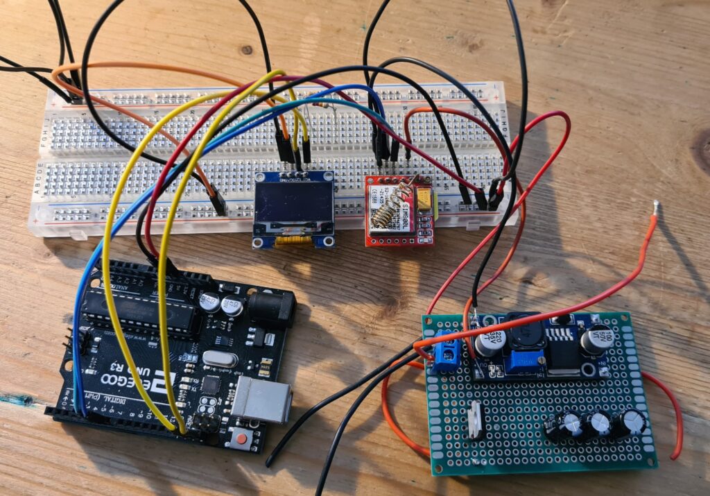
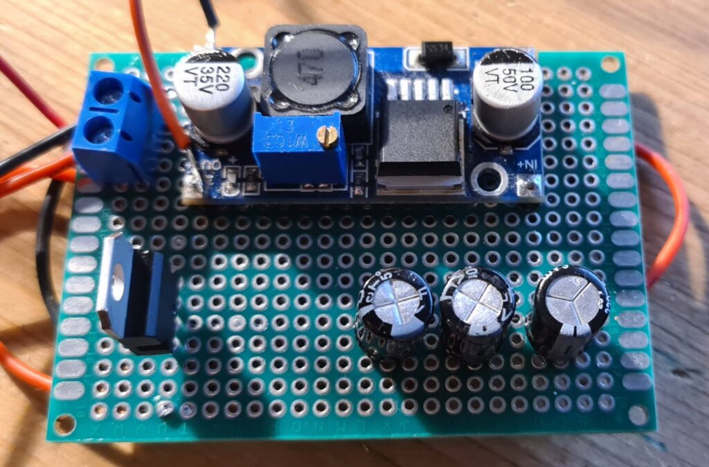
Note on the capacitors: in the photo of our power-supply board (further down) you’ll see a few capacitors. They are not connected to the circuit: they’re leftovers from reusing an old perfboard, and they’re not needed for the module to work. We left them visible in the photo just for transparency’s sake — feel free to ignore them.
Note on the 20 kΩ resistor: an earlier version of this article listed this value inconsistently in two different places (20 kΩ and 22 kΩ). The correct value, consistent with the reference schematic linked further down, is 20 kΩ.
How much the module draws
Let’s start with a table showing current draw (in mA and A) for each specific operating mode:
| Mode | Frequency | Current consumption |
|---|---|---|
| Power down | 60 µA | |
| Sleep mode | 1 mA | |
| Stand by | 18 mA | |
| Call | GSM850 | 199 mA |
| Call | EGSM900 | 216 mA |
| Call | DCS1800 | 146 mA |
| Call | PCS1900 | 131 mA |
| GPRS | 453 mA | |
| Transmission burst | 2 A |
Current consumption table by operating mode (source: SIM800L datasheet).
Powering the module: where almost everyone gets stuck
The supply voltage range for this module is roughly 3.4V to 4.4V. In our first project with this module (the low-battery GSM alarm, currently only available in Italian), we’d originally planned to power it through a simple voltage divider off an LM7805 regulator.
Looking at the consumption table above, though, it becomes clear that — contrary to what we assumed, and to what we’d read in some articles online — it is simply not possible to power the module this way. Let alone by using Arduino’s 5V pin directly: during transmission bursts the module can draw up to 2A, far more than Arduino’s 5V pin can supply.
We’ve seen other makers online use a 3.7V LiPo battery. That would indeed have worked, but for a permanently-connected device we’d also have had to handle battery charge management, likely with a dedicated LiPo BMS.
We went with a DC-DC step-down instead, which works well both on the test bench and in the original project that drove the need for this module in the first place. Since it comes in handy often, we built ourselves a small permanent power-supply module (on a perfboard) made of a plain LM7805 — which, as a reminder, is a step-down regulator with a fixed 5V output — to power any Arduino board, plus an adjustable-output DC-DC step-down (set to 4.2V in our case) for the SIM800L.
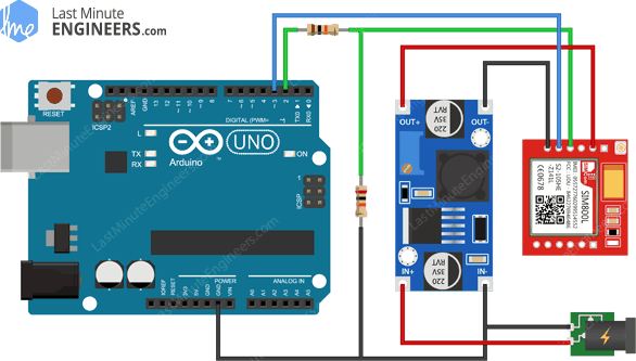
In practice, it’s essentially a build of the schematic we found in this article: lastminuteengineers.com/sim800l-gsm-module-arduino-tutorial
Pins used in this project
This is not the full SIM800L pinout — for that, refer to the official datasheet linked further down — just the pins we wire up in this specific project:
| SIM800L pin | Connected to | Role in this project |
|---|---|---|
| VCC | DC-DC step-down output (~3.8-4.2V) | Power — never Arduino’s direct 5V pin |
| GND | Common ground with Arduino and the power supply | Ground reference |
| TX | Arduino digital pin D6 (SIM_TX_PIN) | Data from the module to Arduino |
| RX | Arduino digital pin D5 (SIM_RX_PIN), through a 10 kΩ/20 kΩ divider | Data from Arduino to the module — needs 5V→3.3V logic-level adjustment |
| DTR | Arduino digital pin, set HIGH | Sleep/wake-up control of the module (see dedicated section) |
Serial connection with Arduino

A quick note on the Elegoo UNO R3 board, a clone of the original Arduino UNO R3: it uses the same ATMEGA328P chip as the original, but its USB-to-serial converter uses the CH340G chip, whose drivers aren’t bundled with the standard Arduino IDE install. They need to be installed separately — instructions and links are in this article (Italian): makerslab.it/installare-i-driver-per-il-modulo-ftdi-ch340g-per-i-cloni-di-arduino
Logic levels: why you need a voltage divider
Here’s a quick aside on logic levels, which aren’t the same on the control board and on our SIM800L module.
We can’t wire the module’s Rx pin directly to an Arduino digital pin, because the Arduino UNO runs at 5V logic while the SIM800L module runs at 3.3V logic.
To step the signal down from 5V to 3.3V we use our (by now dear and inseparable) voltage divider: a 10 kΩ resistor between Arduino’s digital pin and SIM800L’s Rx pin, and a 20 kΩ resistor between SIM800L’s Rx pin and GND. Dedicated 5V-3.3V logic-level converters also exist — you’ll find one linked in the components section.
The sketch for talking to the module
Before we get to sending an SMS or reading the module’s status, we need to load a sketch that lets us talk to the SIM800L and run our own experiments.
We used a simple sketch that sends to the GSM module whatever we type into the serial monitor, and prints on the serial monitor whatever the GSM module sends back to the board.
Configuration and initialization
//Include the library for serial communication between Arduino and the SIM800L
#include "SoftwareSerial.h"

//Define the Arduino pin wired to the Sim800L's TX pin — D6 in our case
#define SIM_TX_PIN 6
//Define the Arduino pin wired to the Sim800L's RX pin — D5 in our case (mind the divider!)
#define SIM_RX_PIN 5
//Set up a software serial port on the SIM800L's TX and RX
SoftwareSerial serialSIM800(SIM_TX_PIN, SIM_RX_PIN);

void setup() {
  //Initialize the serial connection between Arduino and the PC
  Serial.begin(57600);
  //Initialize the virtual serial connection to the SIM800L
  serialSIM800.begin(57600);
  delay(500);
}
(Fixed compared to the previous version: the comment above SIM_RX_PIN still said “TX pin” — an obvious copy-paste leftover.)
Two-way dialogue loop
void loop() {
  //Write to the Arduino-PC serial whatever you read from the SIM800L's TX pin
  if (serialSIM800.available()) {
    Serial.write(serialSIM800.read());
  }

  // AUTHOR TODO: the matching block that forwards to the SIM800L whatever
  // is typed on the serial monitor goes here (it was hidden behind the
  // site's navigation bar in the source PDF). Presumably:
  // if (Serial.available()) {
  //   serialSIM800.write(Serial.read());
  // }
}
Status indicators
Now that it’s wired up and powered, we can insert the SIM card and check the status LED:
- one blink every 1 second: module active but not yet registered on the network;
- one blink every 3 seconds: module active and successfully registered on the network.
For more detail on what’s going on, we need to send a few AT commands and look at the responses.
Key AT commands to check the wiring
The full command reference is available in the documentation (linked further down). Here we only cover the main commands — the ones that let us confirm the wiring is working and the module is ready to use.
AT — checking the serial link
10:40:20.795 -> AT
10:40:20.796 -> OK
The first command to send to check the dialogue between Arduino and the SIM800L. If you don’t get “OK” back, there’s a problem with the wiring between the SIM800L’s RX/TX pins and Arduino’s pins.
AT+CSQ — signal quality
10:40:25.735 -> AT+CSQ
10:40:35.980 -> +CSQ: 16,0
Used to check signal quality. The first number (16 in our case) should fall between 2 and 30, which corresponds to a signal between -110 and -54 dBm.
AT+CCID — reading the SIM
10:40:35.983 -> AT+CCID
10:40:42.373 -> 8944502206206365147
This is the SIM’s ICCID. We use it to confirm the module is correctly reading the inserted SIM’s data.
AT+CREG — network registration status
10:40:46.745 -> AT+CREG
10:40:50.949 -> +CREG: 0,5
We check whether the module successfully registered on the network. In our test the second number (5) means “registered, roaming”: if you’re using a SIM that operates as an MVNO riding on another carrier’s network, that’s expected. But if you’re using a SIM issued directly by the network operator and still get 5 instead of 1 (registered, home network), it’s worth checking with your carrier.
AT+COPS? — network operator
10:40:50.949 -> AT+COPS?
10:40:57.062 -> +COPS: 0,0,"Wind Telecom SpA"
10:40:57.065 ->
10:40:57.065 -> OK
We also check which operator we’re connected to, and indeed it confirms the above.
Sleep & wake-up
We wrote two dedicated functions, one to put the module to sleep and one to wake it back up. The prerequisite is always that the SIM800L’s DTR pin is wired to an Arduino output pin, set HIGH.
sim800sleepmode() — putting the module to sleep
void sim800sleepmode(){
  serialSIM800.println("AT+CSCLK=2");
}
Putting it to sleep only takes one AT command (AT+CSCLK=2) with the DTR pin set HIGH. The catch is that once it’s in sleep mode, the module stops responding on the serial port.
sim800wakeup() — waking the module back up
void sim800wakeup(){
  digitalWrite(DTR_PIN, LOW);
  delay(200);
  digitalWrite(DTR_PIN, HIGH);
  serialSIM800.println("AT");
  serialSIM800.println("AT+CSCLK=0");
}
To wake it from sleep mode you need to pull the DTR pin LOW (we hold it there for 200 milliseconds), then send any AT command. Only after that can you send AT+CSCLK=0 to restore normal operation, i.e. disable DTR-controlled sleep.
(Fixed compared to the previous version: the text said AT+CSCLK=1, which didn’t match the code above.)
Sending an SMS
To send an SMS we can either use the serial-interface sketch and type the commands directly into the serial monitor, or write a dedicated sketch that sends the SMS on its own.
We used the first option for testing. Once we confirmed everything worked correctly, we’ll add the command lines for sending the message into the monitoring and low-battery alarm program for the motorbike, which we’ll cover in a dedicated article.
11:26:23.833 -> at+cmgf=1
11:26:30.783 -> OK
11:26:30.783 -> at+cmgs="+39xxxxxxxxxx"
11:26:46.372 -> > test message
11:26:53.794 -> >
11:27:12.950 -> OK
Frequently asked questions
Are the capacitors shown in the photos necessary?
No. In the photo of our power-supply board you’ll see a few capacitors, left over from reusing an old perfboard: they’re not connected to the circuit and aren’t needed for the module to work.
Does the module work with any SIM and any carrier?
In our experience, and that of several readers in the comments, results vary depending on the SIM/carrier/power-supply combination. By far the most common cause of trouble is the power supply: without a source able to deliver a couple of amps at around 3.8V, the module either fails to register on the network or replies with garbled characters on the serial port.
Can I wire the SIM800L directly to a board that natively runs at 3.3V (e.g. NodeMCU/ESP), without a voltage divider?
The voltage divider described in this article only adapts the logic level from 5V (Arduino UNO) to 3.3V (SIM800L): with a board that already runs at 3.3V, you don’t need it for that reason. That alone doesn’t guarantee it’ll work, though — as above, the most common issue remains the module’s power supply, not the logic level.
Can I power the module from a 3.7V LiPo battery instead of the step-down?
Yes, we’ve seen other makers do exactly that. For a permanently-connected device, though, you also need to account for battery charge management (e.g. with a dedicated BMS), which is what led us to go with the DC-DC step-down instead.
How can I tell if the module has registered on the network without reading the serial output?
Watch the status LED on the board: one blink per second means the module is active but not yet registered on the network; one blink every 3 seconds means it has registered successfully.
Project files
- Serial-interface sketch used for testing: INSERT-REPOSITORY-OR-INO-FILE-LINK
- Wiring schematic: INSERT-EASYEDA-SCHEMATIC-OR-HIGH-RES-IMAGE-LINK
Disclaimer
If powered incorrectly, this module can be permanently damaged — it happened to us more than once during testing, before we landed on the right power-supply combination. If your final project involves wiring it permanently into a vehicle or an electrical system, pay particular attention to the power-supply and logic-level points described above.
This article is for informational and hobbyist purposes only: we make no guarantees about the correctness of the schematics, code or procedures described, and building this project is done at the risk and responsibility of whoever carries it out. The device described here is not a certified or type-approved instrument. For full details, see our Terms and Conditions (Italian).
Documentation
It’s essential to check the module’s official documentation and AT command reference, which we share here:
- SIM800L datasheet – PDF with the full hardware specifications;
- AT commands manual – PDF with every AT command, the language used to talk to the module.
Join our community and help us grow!
Did you enjoy this article? Share your thoughts in a comment! It helps us keep improving our content.
Do you have a blog or website? Share the link in the comments and we’ll go check it out. Let’s help each other grow!
Got an idea but don’t know where to start? Get in touch!
Further reading
To get everything working, we consulted a number of sites — here’s the full list:
- makerslab.it – CH340G drivers (Italian);
- treccarichi.net – the comments highlight the power-supply issue we later confirmed experimentally with our prototype (Italian);
- electroyou.it – a very interesting discussion (Italian);
- lastminuteengineers.com – one of the best and most interesting write-ups on this;
- iemma.it – key reading on the voltage divider for adapting logic levels between Arduino and the SIM800L (Italian);
- pijaeducation.com
- andino.systems
- raviyp.com – a very interesting article on managing sleep mode, and especially software wake-up.
0 Comments